arduino 联接蓝牙模块
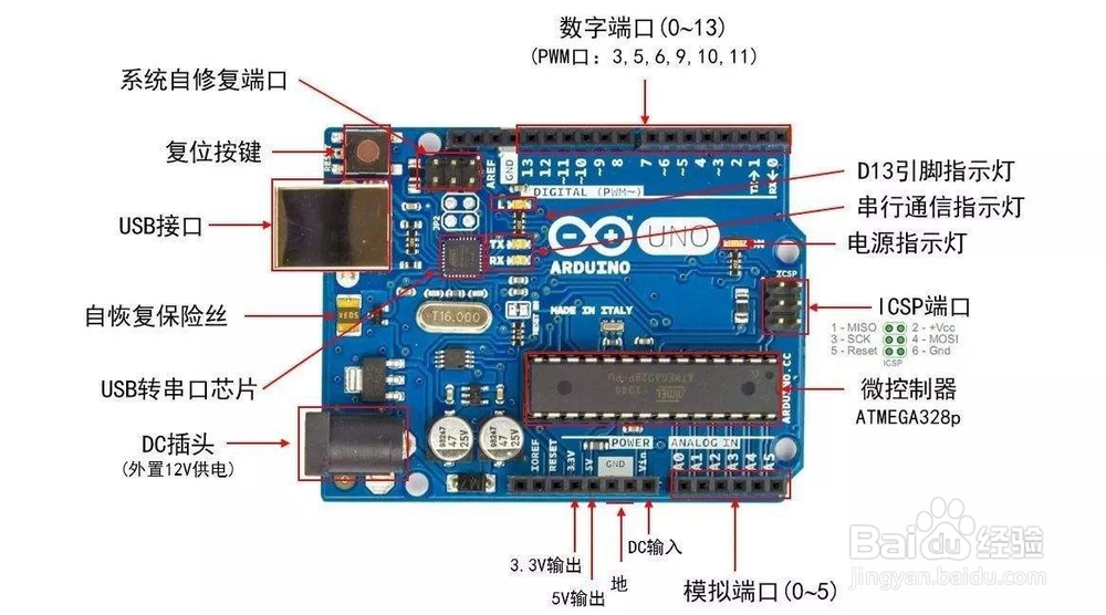
1、在连接硬件之前,大家仔细看这块开发板的硬件连接说明。硬件连接,装备好一个ARDUINO板一个,USB线一根,这里USB线充当电源线,因为ARDUINO板电压为3.V-12V都可以用。准备好后按图连接。
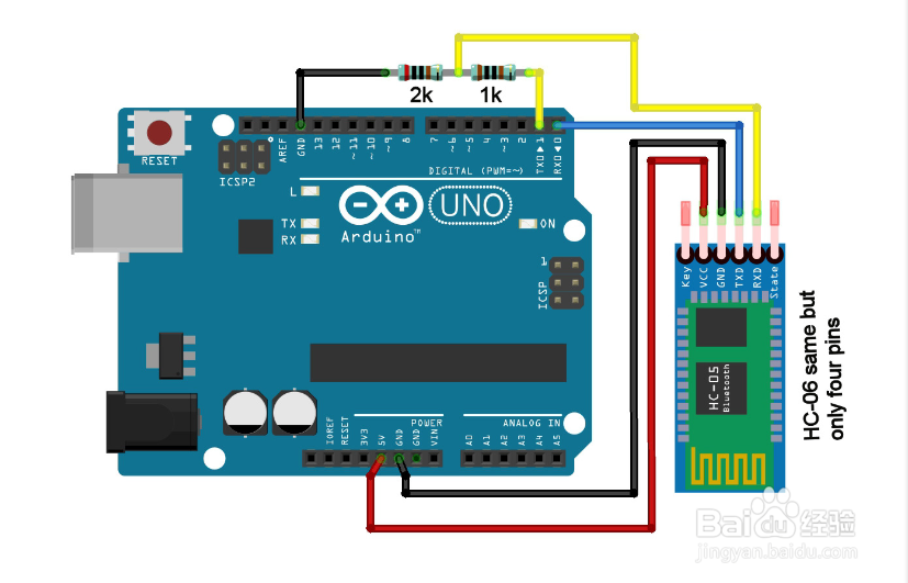
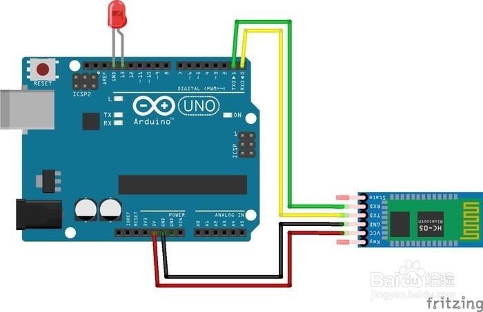
2、基本连接如下图所示。安全起见,加上二个电阻如果仅是低电压的测试也可以按图二连接测试具体的接法,一定要注意开发板收发两个端的接法,如图三所示

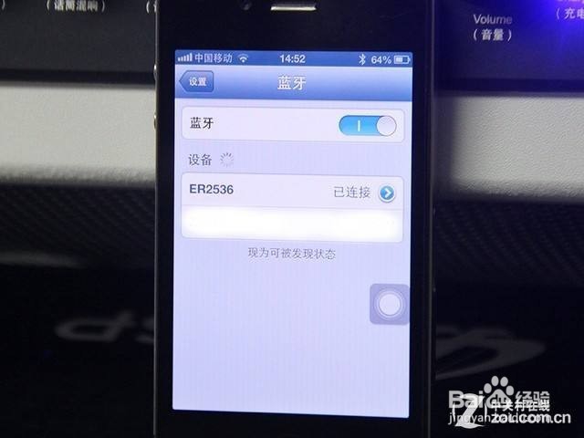
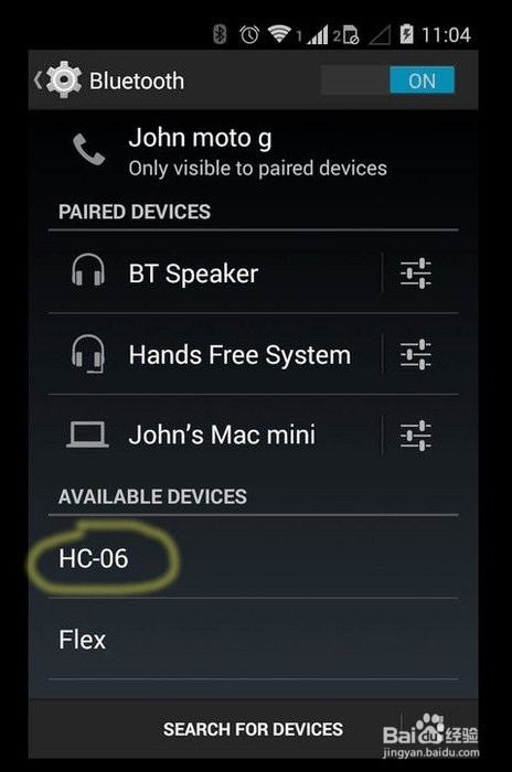
3、正确检查无误后连接USB上电会看到蓝牙模块有红色指示灯闪烁。这时,打开你的智能手机,以ANDROID手机为颖蓟段扛例。打开蓝牙开关并搜索找到相应的模块后如果是HC-06那么点击后连接配对,一般会要输入配对密码,一般为1234或0000,输入后配对成功。便可以操作了。
4、硬件连接后,连上电脑ARD曷决仙喁UINO IDE并上传相关代码测试。代码片断为:#include <SoftwareSerial.h>SoftwareSerial B皈其拄攥T(10, 11);// creates a "virtual" serial port/UART// connect BT module TX to D10// connect BT module RX to D11// connect BT Vcc to 5V, GND to GNDvoid setup(){ // set digital pin to control as an output pinMode(13, OUTPUT); // set the data rate for the SoftwareSerial port BT.begin(9600); // Send test message to other device BT.println("Hello from Arduino");}char a; // stores incoming character from other devicevoid loop(){ if (BT.available()) // if text arrived in from BT serial... { a=(BT.read()); if (a=='1') { digitalWrite(13, HIGH); BT.println("LED on"); } if (a=='2') { digitalWrite(13, LOW); BT.println("LED off"); } if (a=='?') { BT.println("Send '1' to turn LED on"); BT.println("Send '2' to turn LED on"); } // you can add more "if" statements with other characters to add more commands }}
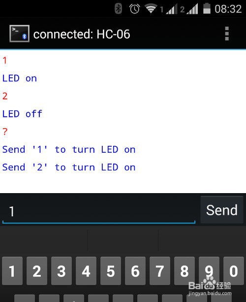
5、把上图的代码上传至开发板后,用手机连上这块开发板的蓝牙后,可以通过手机发射指令来查看效果了。