通信原理Matlab仿真教程
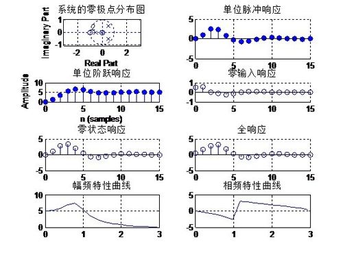
1、解:程序如下:a=[1 -0.5 0 0.3 -0.005];b=[0 1 2 1 0];subplot(4,2,1);zplane(b,a);title('系统的零极点分布图');grid on;%绘制系统的零极点图[hn n]=impz(b,a,16);subplot(4,2,2),stem(n,hn,'filled');title('单位脉冲响应');grid on;%绘制单位脉冲响应subplot(4,2,3);stepz(b,a,16);title('单位阶跃响应');grid on;%绘制单位阶跃响应N=16;n=0:N-1;x=exp(-n);x0=zeros(1,N);y0=[1,-1];xi=filtic(b,a,y0);y1=filter(b,a,x0,xi);xi0=filtic(b,a,0);y2=filter(b,a,x,xi0);y3=filter(b,a,x,xi);[h w]=freqz(b,a,16);subplot(4,2,4);stem(n,y1);title('零输入响应');grid on;%绘制零输入响应subplot(4,2,5);stem(n,y2);title('零状态响应');grid on;%绘制零状态响应subplot(4,2,6);stem(n,y3);title('全响应');grid on;%绘制全响应subplot(4,2,7);plot(w,abs(h));title('幅频特性曲线');grid on;%绘制幅频特性曲线subplot(4,2,8);plot(w,angle(h));title('相频特性曲线');grid on;%绘制相频特性曲线
2、结果:
声明:本网站引用、摘录或转载内容仅供网站访问者交流或参考,不代表本站立场,如存在版权或非法内容,请联系站长删除,联系邮箱:site.kefu@qq.com。
阅读量:38
阅读量:45
阅读量:92
阅读量:72
阅读量:88